
Product Design
| Entry Number | Description |
| Exercises 1 2 3 4 | Initial Sketches Bell Design (FEA) Plotter Exercise 4-Bar Tutorial |
| Assignments 5 6 7 8 | Sketching (Big Belly) Skateboard Design 2.5 DOF System Mechanism Design |
1. Initial Sketches
Objective: One often overlooked skill of an engineer is the ability to communicate without people outside of the profession. Design sketches are used to communicate in and outside the field. The purpose of this exercise is to practice that skill.
Context: Before completing this sketch, the class was instructed in the basis of this communication style. Good sketches use a rational layout, firm tracing, different line weights, notes when necessary, and occasionally color to improve the clarity of communication.
Specific task: The goal of this exercise was to propose an idea to fix street flooding due to leaves covering drains in autumn as shown below.

Thought before design: My goal in this design was to make something practical that could be adopted by the City of Boston to prevent leaves from causing street flooding.
Design process: When brainstorming for this problem I thought of a few high-tech solutions such as a conveyor belt that continuously moved leaves off of the drain into a trash bin below the sidewalk. I realized that solution was impractical though and it was unlikely for a municipality to adopt it. My next idea was to put a board slanting from the curb over the drain such that people could cross without getting their feet wet. That would cause additional problems though because cars would drive over it.
Results: The final solution I came up with is shown below.
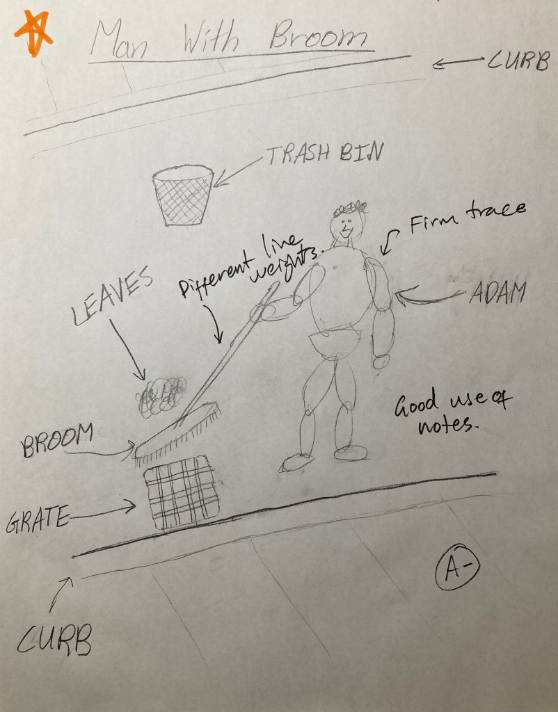
Evaluation: My solution involved manual labor – pay public servants to sweep the leaves off of the grates. It is not a very high-tech design, but it is practical. One thing I could have done differently was use a firmer trace on the man and different line weights on the broom to distinguish exterior lines.
2. Bell Design
Objective: The purpose of this exercise was to use Finite Element Analysis in Solidworks to analyze the vibration of a bell and determine the sound a given geometry and material would make.
Context: Solidworks provides a high-quality vibration simulation tool that was used for this exercise.
Specific task: The design parameters for the bell was to use the below cross-section with a maximum diameter of approximately one meter.

Thought before design: To design a bell with the above geometry I modeled the outside of the bell using a revolved boss/base. I used bronze for the material because it is commonly used for large church bells.
Design process: The next step was to analyze the frequencies produced by the bell. I used Solidworks Simulation to find the first twelve frequencies the bell would vibrate at and MATLAB to turn those frequencies into an audible sound. In MATLAB, I made the initial frequencies loud and die quickly. The later frequencies would be quieter but die slower.
Results: The results are plotted below and the sound produced is attached.
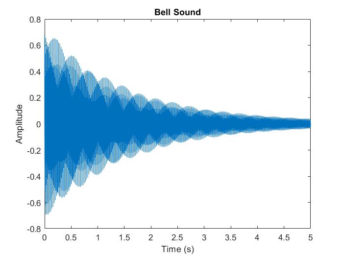
Evaluation: Based on my experience with large bronze bells, the sound produced by Finite Element Analysis and MATLAB code is an accurate estimation of how the bell would sound.
3. Plotter Exercise
Objective: The objective of this exercise was to gain experience using an Arduino to control a stepper motor.
Context: In class, we were taught how a stepper motor is controlled by running current through successive electromagnets to spin an axis.
Specific task: The task we were given was to draw a square on a cartesian coordinate system made from three lead screws attached to stepper motors.
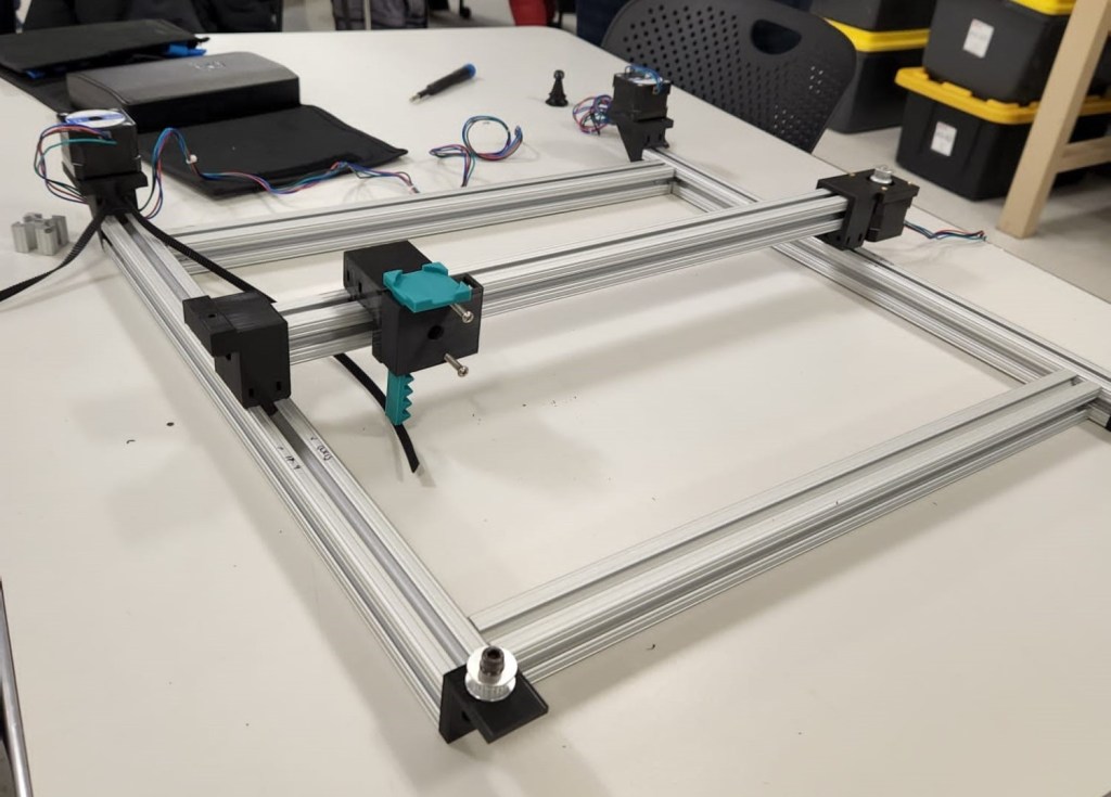
Thought before design: Before creating the product, we were instructed to make the three lead screw systems in groups of 3-4 people. We then came together to assemble the final product.
Design process: The base for the lead screws was made of foamboard. We hot glued the pieces together and mounted the hardware.
Results:
Evaluation: This was an effective proof of concept, but we did not perfect it. There was some friction between the marker and the paper when drawing the final line that prevented it from completing the square.
4. 4-Bar Tutorial
Objective: The objective of this exercise is to gain experience modeling 4-bar mechanisms and analyzing their motion.
Specific task: The goal was to complete the assignment above by creating the four-bar mechanism described and determine the maximum value of the motor torque, the angle of the crank for which the motor torque is maximum in each cycle, the maximum vertical force exerted on each bearing, and the minimum motor power required to move the Crank at a constant 600 rpm.
Design process: The material selected is plain carbon steel and the motor (not shown) was placed on the bottom left joint spinning at 20 rpm.
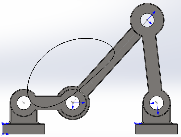
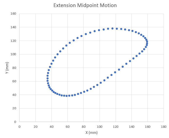
Results: The path of the midpoint of the central bar is traced above. The results are plotted below.
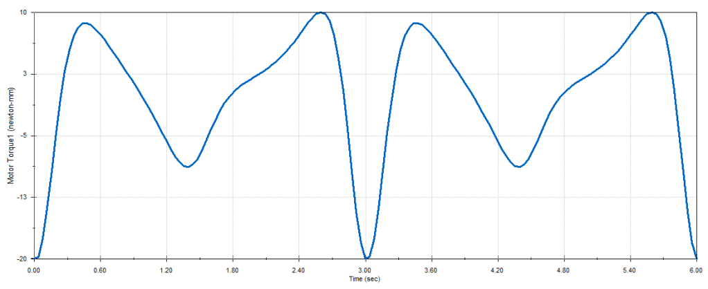
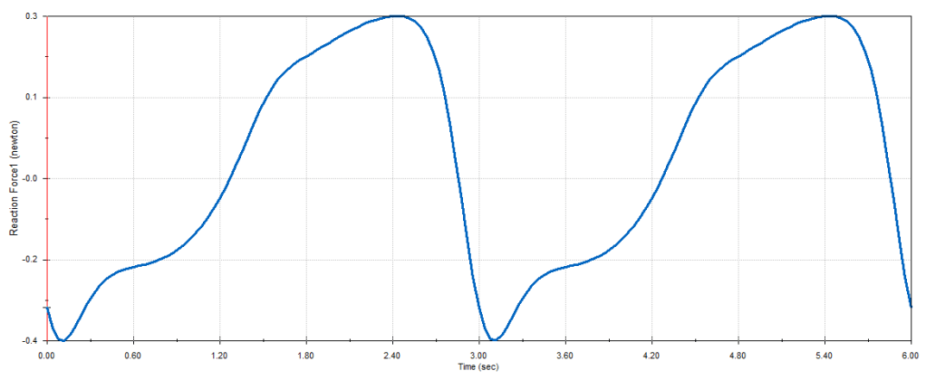
The motor torque and the vertical force exerted on each bearing is shown below.

Finally, I ramped the rpm of the motor up to 600 and plotted the power consumption. This is shown below.

Evaluation: The greatest magnitude of the motor torque at 20 rpm is 20 Newton-mm and that occurs when the crank is at 0 degrees or the position shown in the picture above. The maximum value is 10 Newton-mm and that occurs at 315 degrees.
The greatest magnitude of vertical force exerted on the left and right bearings are 0.4 Newtons and 0.3 Newtons respectively. The maximum force exerted on both is 0.3 Newtons.
The minimum motor power required to move the crank at a constant speed of 600 rpm is 470.35 Watts.
The torque sometimes drops into the negatives. During those time intervals the combined gravitational force on the other links is pushing the crank with the direction of its motion. Therefore to keep the same rotational speed the motor must work against gravity and push the opposite direction.
5. Sketching (Big Belly)

Objective: The Big Belly Solar trash compactor is considered unhygienic by some as the user must touch the handle to operate it. It can also lose power if the solar panel is covered by snow. Additionally, not all common trash items fit in the receptacle.
Context: This is a relatively common problem in the Boston area.
Specific task: Design a new solar-powered trash compactor that does not have these drawbacks.
Design process: My immediate thought was that the solar panels would not be obstructed by snow if they were angled.
Results:
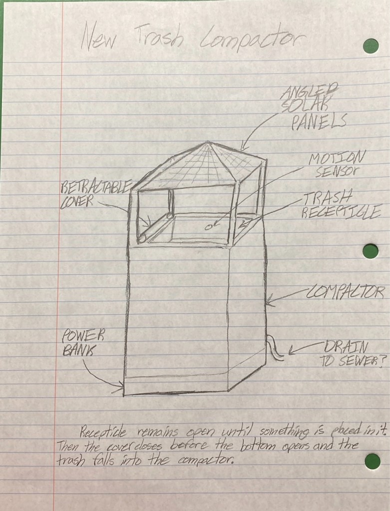
Evaluation (Discussion): There is a chance of precipitation entering the compactor through the top, so I have also included a drain to the sewer.
6. Skateboard Design
Objective & Constraints: The goal of this project is to design a skateboard deck that can support a 180 lbs. man with size 12 feet. To factor in things like jumping and turning, a factor of safety of three was chosen.
Summary of Relevant Information: Skateboards are generally 28-32 inches long and 7.5-8.25 inches wide. Skateboards are commonly made by gluing layers of plywood together.
Design Decisions and Model: Skateboards generally are concave upwards in order to facilitate turning by leaning to one side, so my initial sketch shown below in Figure 1 takes that into account with a slight bend.
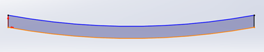
Figure 1
Another important consideration is how the board turns up at the ends to allow the user to “pop” the board up to do tricks. The sketch of that is shown below in Figure 2.
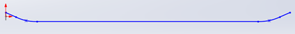
Figure 2
The geometry must also have rounded ends and sides. The product is shown in Figure 3.
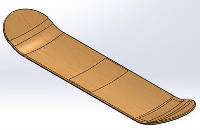
Figure 3
Material Selection: The hardest part of this project was deciding what material to use for the deck. The first material I considered was Balsa wood, but it did not work because it was not strong enough and the weight of the man would break the board by exceeding the yield strength.
The next material I considered was stainless steel because it is much stronger. This would work in theory, but is comparatively dense, so I eliminated that choice as well.
My third consideration was aluminum because it is stronger than wood but lighter than steel. The type of aluminum I settled on was AL6063-T6 because it is stronger and stiffer than many steals while keeping the light weight. This was very nearly my final decision before I made another discovery.
The final choice for the material was sugar maple wood. It is lighter than aluminum and stronger than balsa wood, making it the perfect material for the application. Also, its elastic modulus is less than that of AL6063-T6 which is good because it allows the user to get a better “pop” off the tail.
FEA: I conducted Finite Element Analysis for each of the above materials to help with selection. Here I will discuss how it was done and give the results for the material selected.
A man with size 12 feet would easily cover the board horizontally and a size 12 shoe is approximately 4.1 inches wide, so that was the size of the shapes I used apply force. To simplify the model, I estimated the shape of a foot as a rectangle. I placed one foot in the middle of the board and one foot on the tail, the standard position assumed when one performs a trick. The force applied was three-halves the weight of the person per foot (3x 180lbs total) in order to account for the Factor of Safety.
The final thing to decide before running the model is how the board is constrained. The trucks are affixed to the bottom near each end but before the nose and tail bed. Truck are generally 2×3 inches each.
The results of the analysis using these assumptions are shown below. Figure 4 shows the stress, Figure 5 shows the displacement, and Figure 6 shows the strain.

Figure 4 – stress
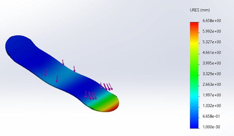
Figure 5 – displacement
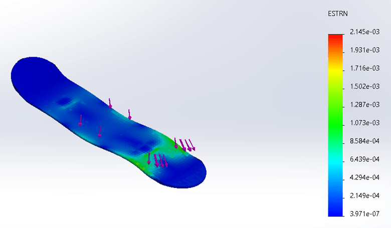
Figure 6 – strain
Design Optimization: Using the FEA results I was also able to find the ideal thickness of the skateboard while staying within the constraints of the assignment. The ideal thickness for this board is 0.39 inches. The constraining factor was deflection capped at 0.375 inches. At a thickness of 0.39 inches, the maximum deflection was 0.26 inches.
Conclusion: From this project, I came to understand that skateboard design is a surprisingly technical subject that requires a lot of background information and complex modeling to get right. Also, sugar maple wood is a good choice because skateboard decks are frequently made from maple wood.
7. 2.5 DOF System
Objective: The purpose of this assignment was to design and build a 2.5 Degree of Freedom system that performs a task.
Context: The materials made available included 8020 aluminum extrusion, stepper and servo motors, pulleys, linear guides, belts, solenoids, and servomotors.
Specific task: The task my group decided to perform was to play a game of chess. The goal was to create an autonomous chessboard so that a person could play chess in real life against a computer.
Thought before design: The first decision that needed to be made was whether we wanted to move the pieces using a claw or a magnet. We used a magnet because the design would fit below the board and was less likely to get in the way of the player.
Design process: When designing the cartesian motion system we used a similar setup as the plotter exercise (assignment 3). The difference would be that this time belts and pulleys would be used instead of lead screws. We made that substitution because it meant we could move the axes faster with the sacrifice of some precision.
A photo of our CAD design is shown below.

We used a rack and pinion to extrude the magnet up towards to the pieces. This allowed the magnet to come close enough to the magnetic chess pieces to move them from beneath the board.
We modeled and 3D printed sliders for the 8020 rail and attached them to the belt. See video footage below.
Once we got one axis working, the next step was to put the three axes together to complete the cartesian motion system. The photo below shows the moving axes assembled without belts.
There were some issues with the system at first. The pinion was too large for the housing and got stuck, so we adjusted the CAD and printed a few models before getting it right. We also found that there was a lot of friction between the slider and the track if opposing sides were not well aligned, so we learned to be careful with assembly. We also had some difficulties finding an appropriately sized magnet such that it could move pieces from beneath the board but not move neighboring pieces. Eventually, we got it all working. Below is a video of a prototype successfully moving pieces.
We used AI to compute the chess moves, but the final step involved developing code that translated those moves into motor commands to physically move the chess pieces. This step proved particularly challenging, requiring extensive trial and error to ensure the spacing and movements were accurate. Since the system lacked sensors to track piece locations, we aligned the machine and chessboard coordinates manually and input each player’s moves into the program. A link to the code is provided below.
Code: https://github.com/abingeorge07/autonomousChess
Results: Below is a link to a video of the final project in action.
Evaluation: We met the objective of the assignment and created something we enjoyed as a group. We worked together effectively and found methods to navigate issues as a team.
We did not have the time and resources to optimize our product and make it fully autonomous without the need to type your moves into the computer.
Partners: Abin George, Adam Boldi, Aayush Amrit
8. Mechanism Design
Objective: The purpose of this assignment was to gain additional experience designing four-bar mechanisms performing simple tasks.
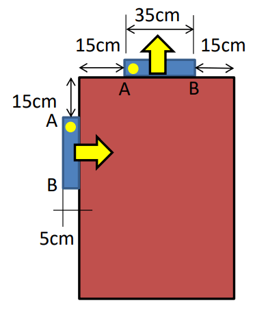
Specific task: The task given was to design a four-bar mechanism that controls a new design for a trash container. The idea was that a user deposits trash on top of a tray, and it is automatically taken away and thrown into an opening in the back of the bin. The specifications of where the link starts and ends are shown below.
Thought before design: Additional design requirements dictate that the tray could not pass through the body of the trash can and that pivot points had to be on the sides of trash can.
Design process: The first step of the design process was modeling the system in Math Illustrations such that I could try different mechanism skeletons and adjust the degrees of freedom more easily. To find the locations for the pivots I drew an intermediate step above and to the left of the trash can and found perpendicular bisectors between the initial starting points and the intermediate step. Using the places where these bisectors intersected, I was able to construct a mechanism that moved the middle link in the desired manner. The problem was that one of the pivot points was outside the required area and would require an extension from the trash bin. This was not an option, so I had to brainstorm about how else to design it.
Finally, I realized that the pivots on the tray (or middle link) do not have to be at the endpoints – they could be anywhere on the tray. This immediately opened up my options. I moved the two points closer together and went through the same process again. This time I was able to get my pivot points in the required area. I noticed at this point that in order to make the link spin in the direction I wanted it to, the links had to pass through a co-linear stage which meant that the sum of two links had to equal the sum of the other two.
Once I had my design ready in Math Illustrations, I translated it to Solidworks. To do this I set the origin in Math Illustrations at the bottom left hand corner of the rectangle I drew to represent the trash can. From there I could simply read off the lengths of the links and the exact coordinates of the pivot points. From hole to hole, the links were 30.49 cm, 10.00 cm, and 34.55 cm. The coordinates of the pivot points were (5.622, 79.378) and (15.562, 69.438), which makes the length of the last link 14.05 cm, consistent with collinearity.
There was a small amount of error introduced by coordinates defining the length of the fourth link instead of it being defined directly. This meant the rotation of the mechanism was not quite as smooth in Solidworks as it was in Math Illustrations. To account for that, I made one of the holes in the tray a very short slot to give it just a tiny bit of wiggle room.
To put together the final motion study, I measured the angle the rotation would need to go through based on the driving link. I elected to make the driving link the one on the right side which is indicated with a small red arrow in the video below. I measured the driven angle to be 206 degrees, so I made an oscillating motor travel 206 degrees from the displayed starting position and back at a speed of 0.2 Hertz. That animation is shown below.
Results: Below is a link to a video of my final design of the linkage in operation.
Evaluation: Because of the tiny bit of wiggle room I allowed, a careful eye may notice in my animation that the outgoing travel path is not exactly the same as the returning travel path – the paths traced are not exactly overlapping. I do not see this to be an issue though because I do not expect the trash bin to be exposed to many vibrations that could cause problems. To reduce this effect, one could minimize the error by defining the fourth link by length instead of by coordinate points as I mentioned before. I do not believe this is necessary or even helpful though because when manufacturing the linkage there will be some degree of uncertainty added anyway. Instead, the more cost-effective choice is to allow a bit of wiggle in the mechanism as shown in the animation.
